Part 1 and part 2 covered getting the Raspberry Pi booted up and configured with a basic software stack for developing on top of. With that out of the way, we can focus on wiring up the remaining hardware components. There will be two types of IO devices wired to the Pi – temperature sensors and SSR’s.
Temperature Sensors
The temperature sensors being used are small digital thermometers which communicate using the Dallas 1-wire network protocol. These small sensors look similar to simple transistors with three wires coming out of them. They are commonly referred to by the part name DS18B20 and can be bought individually for around $4 each. However it may be a better deal to pick up a 10 pack instead. You’ll also need a single small 4.7k ohm resistor to connect the sensors. You can find these resistors at any neighborhood Radio Shack store.
The number of temperature sensors you will need depends on how many fermentors you want to monitor at one time. It’s also a good idea to have a sensor monitoring the ambient temperature outside of the fermentors. If you are using a fridge or freezer as a fermentation chamber you may want sensors to measure ambient temperatures both inside and outside of the chamber. Since I’m not using a chamber yet, I’m only using a single ambient sensor plus one for each of the two fermentors I’m monitoring – three total.
With only 3 wires, the sensors are fairly easy to wire up. The Adafruit learning site has a good guide. The ground and power leads can be connected to any of the respective ground and 3v3 GPIO header pins. I chose pin #1 for power and pin #6 for ground. The data lead must be connected to GPIO channel #4 which is pin #7 on the header. Connecting it to any other GPIO channel will not work. The resistor is connected between the power and data leads. It is important to make sure that the ground and power leads are correctly identified. If they are reversed, it is possible for the sensor to overheat and burn out when it is connected. All of the sensors should share the same GPIO wiring.
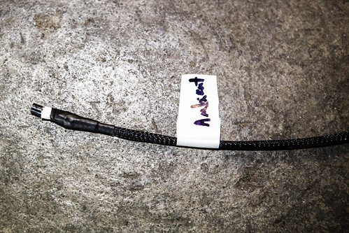
Each sensor has its own unique serial number which is reported by the software driver. The serial number is also etched on the surface of the sensor. Once you have the sensors hooked up and working, you will probably want to record the serial number and label each sensor so that you can more easily keep track of where each one is being used.
SSR’s
The Pi’s GPIO headers can only be used for low power, low current DC devices. This means that any AC powered heaters, fridges or freezers cannot be directly connected and controlled by the Pi. Instead, Solid State Relays (SSR’s) are used. Each SSR has a pair of control input terminals and a pair of output terminals. The input terminals are connected to a GPIO ground pin and one of the GPIO control pins of the Pi. The output terminals are wired into the hot line between a 110VAC power cord and outlet. When the Pi sends a control voltage signal to the SSR, it closes the relay and allows power to flow through the output side to power the outlet where the heater is plugged in.
SSR’s are typically rated based on the current that they can handle. The FermWrap heaters draw 40 watts at 110VAC. Using the standard formula Watts = Amps x Volts, we can calculate that the SSR’s need to be rated for at least 0.36 amps. If you use custom heater sizes, you’ll need to make sure to calculate the number of amps they use and size your SSR’s accordingly. You will ideally want a separate SSR and outlet for every heater for the most accurate control. However, it is possible to have multiple heaters powered from a single SSR as long as the SSR is rated to handle the combined current for all of the connected devices.
I happened to have a few spare 40A SSR’s from Auber Instruments leftover from another project that I used in my build. They’re extremely overrated for this purpose, but can be controlled with any input voltage from 3-32VDC. For this project, any SSR rated for an output of at least 110VAC and 1A and an input voltage of 3VDC will work. An alternative to individual SSR’s might be to use something like the SainSmart 4-Channel 5V Relay Module instead. This option would require a bit more work to successfully wire up, though.
Temperature Control
Each monitored fermentor will have a heater wrapped around it. These heaters are sold pre-assembled by MoreBeer under the name FermWrap. Each heater has an ungrounded 110VAC cord and when plugged in draws 40 watts. They are the same as the heat tape used for heating reptile tanks. If you need more than one or two heaters, it may be more economical to purchase the individual heat tape components and assemble as many as you need yourself. You can also make them in whatever custom length you need this way.
Along with being able to raise the temperature of individual fermentors, you’ll most likely want to lower the temperature or at least maintain a stable ambient temperature. Common solutions are to use a dedicated fridge or chest freezer. Another option would be to build a custom box out of foam board insulation connected to a smaller cube style fridge. The son of a fermentation chiller is one common example of this type of build. While my initial project includes only the heaters, I’m planning on building a custom insulated box as an add on later.
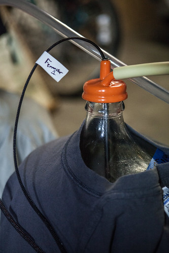
Thermowells
Instead of submersing the temperature sensors directly into the fermentors, I’m using thermowells. These are simple stainless steel tubes with one end crimped that fit through a carboy cap or stopper. The temperature sensors fit neatly inside the tube and are kept safe and dry. You could also choose to submerse the sensor directly instead by either buying premade waterproof sensor cables or making your own. In this case you’d want to verify that the assembly is food safe before using it.
Even with the thermowells, your sensors will need to be attached to some sort of cable. For my cables I stripped an old spare cat5 network cable and soldered three of the individual twisted pair wires to each sensor. You could use telephone wire or any other low voltage copper wire for this instead – I tried to reuse spare parts I already had on hand as much as I could. To finish each cable, I used some 1/8” braided sleeving and heat shrink tubing to secure the ends. I happened to have some braided tubing leftover from another project. While it isn’t strictly necessary to make the cables, it does help make them a bit more rugged, adding a layer of protection to the wires and makes the assembly look a bit more professional.
Prototyping
When prototyping sensors and other devices using the Pi’s GPIO header, you’ll most likely want to use a breadboard and jumper wires to make testing easy. You’ll also need an easy way to connect to the GPIO header on the Pi. A common option is to use the Pi Cobbler breakout board. An alternative approach might be to use an old IDE ribbon cable instead. Floppy drive cables have 34 pins and hard drive cables have 40 pins while the Pi’s GPIO header has 26 pins. Wider cables can fit with the extra pins of the connector hanging off the side of the Pi. You could use a dremel to cut off the portion of the connector that you didn’t need in this case if you wanted. If you choose to repurpose an existing cable, extra care must be taken since some drive cables have some of their pins shorted together internally. If the wrong GPIO header pins are shorted together, it could destroy the Pi. Use an ohm meter to check the continuity between all of the pins to make sure it is suitable for the project before connecting it to the Pi.
Final Assembly
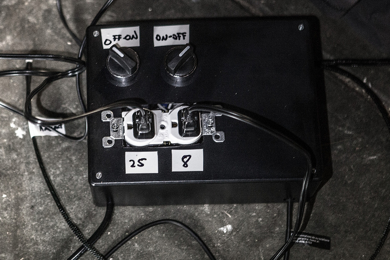
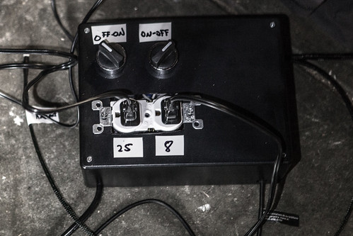
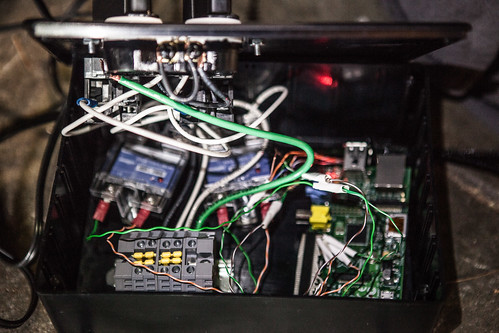
Once I completed prototyping the parts, I assembled the sensor cables and wired everything into an enclosure. I chose a cheap 8x6x3” plastic project box from Radio Shack. The type of enclosure you choose will depend on the specific components you are using. I was able to fit the Pi, two SSR’s, and a terminal block inside the box with a pair of switches and a two gang receptacle mounted to the front of the box. I used a dremel and regular drill to cut all of the holes I needed in the project box. It needed three holes drilled in sides of the box – for the Pi’s power adapter, the AC power cable for the outlets, and the sensor cables. I used a step bit to drill the larger 22mm holes for the switches and a dremel to cut a rectangular hole large enough to mount the receptacle.
I cut the female plug end off a spare grounded PC power cord to use for powering the AC outlets. The switches were wired in between the power and each SSR. This gives me a physical override to disable power going to each outlet. Should there be a SSR failure or some other software malfunction, I can be guaranteed that a heater won’t be inadverntently turned on with the switch. It’s not necessary, but since I already had the switches on hand it seemed like a nice extra safety feature to add.
When wiring power receptacles, you’ll most likely have each outlet driven by a separate SSR. While most two gang receptacles will have two hot and two neutral terminals on each side, the terminals are joined together with a small metal tab. In order to make the outlets independently powered you’ll need to use a pair of side cutters to snip the metal tabs in two to isolate the terminals.